2012 Annual Science Report
 University of Wisconsin
Reporting | SEP 2011 – AUG 2012
University of Wisconsin
Reporting | SEP 2011 – AUG 2012
Project 3A: Stable Isotope and Mineralogical Studies of Banded Iron Formations - O Isotopes by SIMS
Project Summary
During the past year, we have made advances in technique development for analysis of mineral chemistry and stable isotope ratios in minerals. Applications to magnetite in Banded Iron Formation (BIF) have lead to the proposal that silician magnetite forms only in low oxygen fugacity conditions and are thus a signature for the former presence of reduced organic matter. Petrography and in situ analysis of δ18O by SIMS has shown that the earliest quartz cements in 1.85 Ga Granular Iron formation (GIF) consistently have high δ18O showing that earlier reports of more variable compositions included altered material.
Project Progress
Progress in stable isotope analysis at WiscSIMS was summarized by Kita et al. (2011). The effects of sample relief, the location of standards within sample mounts, and crystal orientation can be of critical importance for attaining the highest possible accuracy. New procedures are reported to mitigate each of these problems. In addition, Peres et al. (2012) report the development and testing of a new sample holder for CAMECA ion microprobes that triples the area of a sample mount that can be analyzed at high accuracy from <1 to ~3 cm3. Heck et al. (2011) report new silicon isotope data on quartz in standards and BIF. Our new quartz standard UWQ-1 is shown to be more homogeneous that the commonly used NIST-28.
High silicon contents (1-3 wt. %) have been found in low grade BIFs from many localities, worldwide by Huberty et al. (2012) who studied samples from the Dales Gorge Fm in detail. Silician magnetite can be seen in back-scattered electron images by SEM if contrast is adjusted to make silicates and carbonates appear black (figure, left). TEM and XRD show that Si is substituted with in the crystal structure of magnetite rather than as inclusions. Si-magnetite forms as overgrowths on low-silicon magnetite. Electron backscatter diffraction (EBSD) and forescatter imaging show that individual magnetite grains grow across this boundary and that Si-magnetites grew during evolving burial and metamorphic conditions rather than in late alteration. Huberty et al. show report coupled substitutions and suggest that Si is stabilized in magnetite by low oxygen fugacity requiring the former presence of reduced organic matter and thus that Si-magnetite is a biosignature in BIF.
The secular change of oxygen isotope ratio of cherts in BIF and other lithologies (lower δ18O(quartz) in the Archean) has long been controversial leading to conflicting proposals that Archean oceans were hotter than 75°C; that the Archean ocean was lower in δ18O (< -10‰); or that Archean cherts are systematically more altered than younger rocks. Several recent studies have attempted to resolve pristine vs. altered quartz using in situ SIMS analysis (Robert and Chaussidon 2006, Huberty et al. 2010, Marin et al. 2010). Recently, we selected quartz cements from non-compacted granular ion formation in L. Superior-style BIFs (fig., left) for SIMS analysis and have shown that values of δ18O(quartz) are uniformly at the high end of reported values (fig., right, Cunningham et al., 2012). These results show that lower values represent altered domains and that the δ18O value of the earliest cements in these samples was 24-26‰. While warmer oceans with lower δ18O are not excluded, Cunningham et al. propose that its more likely that the L. Superior BIFs formed in a restricted basin and that the water conditions were been representative of worldwide oceans at 1.85 Ga.
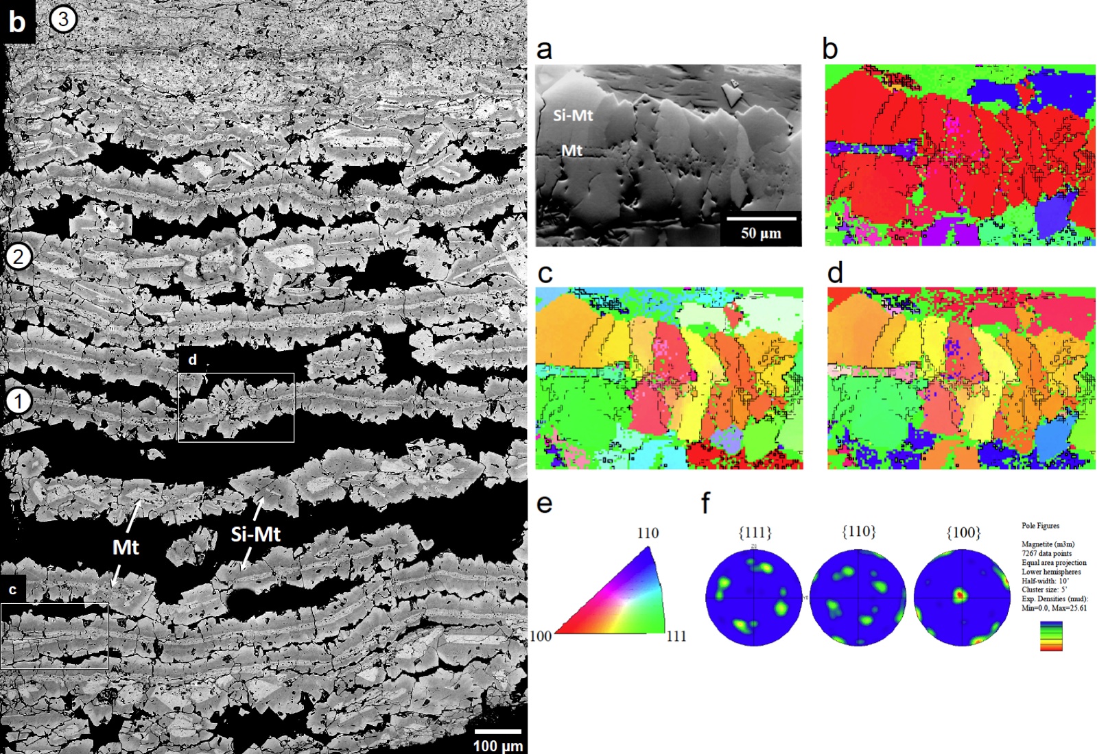
(Left) BSE image of magnetite microlaminae in Dales gorge BIF-3 with brightness and contrast distributed on magnetite only (silicates are black). Three textures are distinguished: (1) magnetite sub-microlaminae with silician magnetite overgrowths, (2) recrystallized magnetite fragments with silician magnetite overgrowths, and (3) a complex intergrowth of magnetite and silician magnetite. Magnetite domains are always surrounded by silician magnetite overgrowths.
(Right) (a) Orientation contrast (OC, or forescatter) image from the same sample. Grayscale values show a patchwork texture of single-crystal domains up to tens of micrometers in size. (b–e) Inverse pole figures (IPFs) for X, Y, and Z show the crystallographic orientations of single-crystal domains (same colors) relative to the X, Y, and Z direction of the image. (b) Magnetite microlaminae are colored almost entirely red indicating that {100} is parallel to the X direction of the image (left to right). (c–d) Single-crystal domains (same colors) are continuous across the sharp chemical boundary between magnetite and silician magnetite. (f) Pole figures show the three primary sets of planes, {111}, {110}, and {100}, in magnetite relative to the sample. There is a strong preferred orientation for magnetite in the BIF and this sample was cut nearly parallel to {100}.
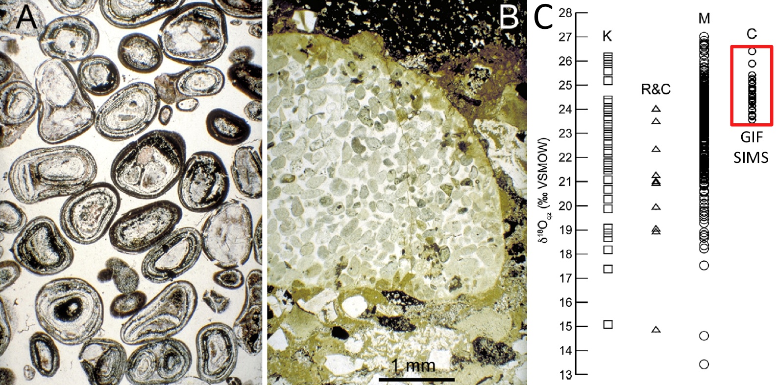
(A & B) Photomicrographs in plane polarized light of GIFs from the Sokoman Iron Formation viewed at the same magnification. (A) Well-sorted framework of chert–hematite oolites. This GIF consists of 66% clasts and 34% cement (clear quartz and chert) by volume with virtually no residual open pore space. (B) A pebble of GIF in a conglomeratic bed deposited by an unusually high energy event. The pebble consists of well-sorted chert–silicate peloids with 29% intergranular quartz and chert cement (clear) by volume. The smooth, well-rounded upper edge of the pebble indicates the cements and peloids were abraded together. The sediment surrounding the pebble is a mix of volcaniclastic detritus (including clear quartz and cloudy feldspar grains) and iron formation intraclasts (including opaque iron oxide-rich flat pebble at top and greenish iron silicates). (C) Comparison of δ18O analyses of quartz from the Gunflint Iron Formation by different researchers. K = Knauth (2005, bulk analysis); R&C = Robert and Chaussidon (2006, SIMS); M = Marin et al. (2010, SIMS); and C = Cunningham et al. (2012, GIF, SIMS).
Publications
-
Cunningham, L. C., Page, F. Z., Simonson, B. M., Kozdon, R., & Valley, J. W. (2012). Ion microprobe analyses of δ18O in early quartz cements from 1.9Ga granular iron formations (GIFs): A pilot study. Precambrian Research, 214-215, 258–268. doi:10.1016/j.precamres.2012.01.016
-
Heck, P. R., Huberty, J. M., Kita, N. T., Ushikubo, T., Kozdon, R., & Valley, J. W. (2011). SIMS analyses of silicon and oxygen isotope ratios for quartz from Archean and Paleoproterozoic banded iron formations. Geochimica et Cosmochimica Acta, 75(20), 5879–5891. doi:10.1016/j.gca.2011.07.023
-
Huberty, J. M., Konishi, H., Heck, P. R., Fournelle, J. H., Valley, J. W., & Xu, H. (2012). Silician magnetite from the Dales Gorge Member of the Brockman Iron Formation, Hamersley Group, Western Australia. American Mineralogist, 97(1), 26–37. doi:10.2138/am.2012.3864
-
Robert, F., & Chaussidon, M. (2006). A palaeotemperature curve for the Precambrian oceans based on silicon isotopes in cherts. Nature, 443(7114), 969–972. doi:10.1038/nature05239
-
PROJECT INVESTIGATORS:
-
PROJECT MEMBERS:
Noriko Kita
Collaborator
F. Zeb Page
Collaborator
Bruce Simonson
Collaborator
Huifang Xu
Collaborator
Philipp Heck
Postdoc
John Fournelle
Research Staff
Hiromi Konishi
Research Staff
Reinhard Kozdon
Research Staff
Takayuki Ushikubo
Research Staff
Jason Huberty
Doctoral Student
Lauren Cunningham
Undergraduate Student
-
RELATED OBJECTIVES:
Objective 4.1
Earth's early biosphere.
Objective 4.2
Production of complex life.
Objective 7.2
Biosignatures to be sought in nearby planetary systems
